Keychron Q2 User Manual
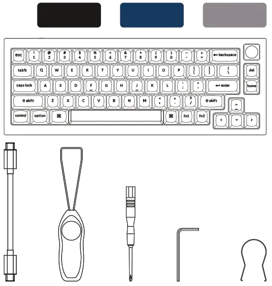
Fully Assembled Version
Keyboard
1x Fully Assembled Keyboard
Including
1x Aluminum Case
1x PCB
1x Steel Plate
1x Sound Absorbing Foam
1x Case Foam
12x Gaskets (8 Installed and 4 in the Box)
4 Sets x Stabilizers
1 Set x Keycaps (PBT Double-shot)
1 Set x Switches (Gateron G Pro)
Cable
1x Type-C to Type-C Cable
1x Type-A to Type-C Adapter
Tools
1x Switch Puller
1x Keycap Puller
1x Screwdriver
1x Hex Key
Barebone Version
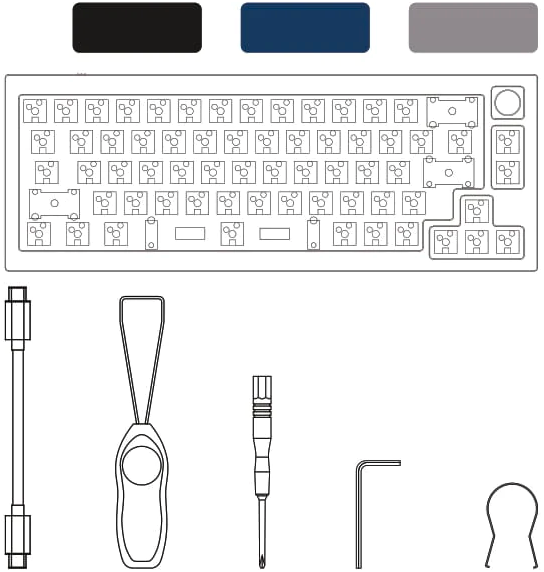
Keyboard Kit
1x Keyboard Kit (Without Keycaps & Switches)
Including
1x Aluminum Case
1x PCB
1x Steel Plate
1x Sound Absorbing Foam
1x Case Foam
12x Gaskets (8 Installed and 4 in the Box)
4 Sets x Stabilizers
Cable
1x Type-C to Type-C Cable
1x Type-A to Type-C Adapter
Tools
1x Switch Puller
1x Keycap Puller
1x Screwdriver
1x Hex Key
QUICK START GUIDE
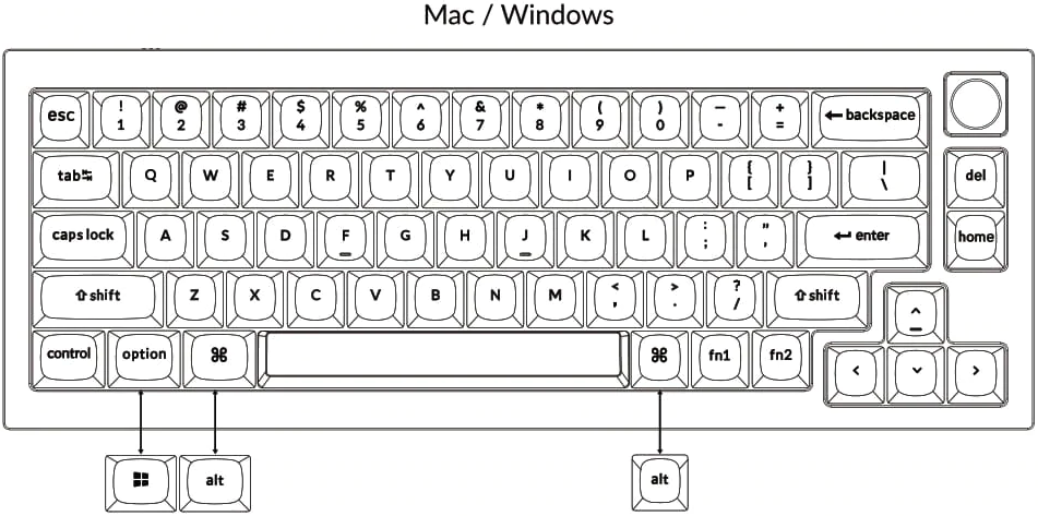
If you are a Windows user, please find the appropriate keycaps in the box, then follow
the instructions below to find and replace the following keycaps.
- Switch To The Right System
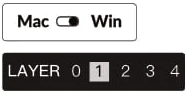
Please make sure the system toggle on the top left corner has been switched to the same system as your computer's operating system.

- The VIA Key Remapping Software
Please visit caniusevia.com to download the latest VIA software to remap the keys. If the VIA software cannot recognize your keyboard, please reach out to our support to get the instruction.

- The Layers
There are five layers of key settings on the keyboard.
The layer 0 is for the Mac system.
The layer 1 is for the Windows system.
The layer 2 is for the Mac Multimedia keys.
The layer 3 is for the Windows Multimedia keys.
The layer 4 is for the Function keys.

If your system toggle is switched to Mac, then the layer 0 will be
activated.
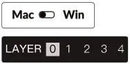
If your system toggle is switched to Windows, then the layer 1 will be
activated.
- Multimedia Key and Function Key
Multimedia keys

Function keys

In order to get Multimedia Key, you need to press fn1 and the following keys:

In order to get Function Key, you need to press fn2 and the following keys:
- The Backlight
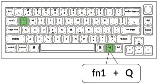
Press fn1 + Q to change the lighting effect.
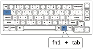
Press fn1 + tab to turn the backlight on/off.
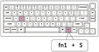
- Adjust The Backlight Brightness
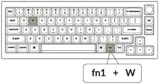
fn1 + W to increase the backlight brightness
fn1 + S to decrease the backlight brightness
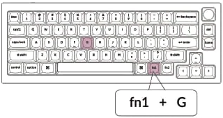
- Adjust The Backlight Speed
Press fn1 + T to increase the light effect speed.

Press fn1 + G to decrease the light effect speed
- Warranty
The keyboard is highly customizable and easy to be rebuilt. If anything goes wrong with any of the keyboard components of keyboard during the warranty period, we will only replace the defective parts of the keyboard, not the whole keyboard.
- Watch The Building Tutorial On Our Website
If you are building the keyboard for the first time, we highly recommend you watch the building tutorial video on our website first, then start building the keyboard yourself.
- Factory Reset
Troubleshooting? Don't know what's going on with the keyboard?
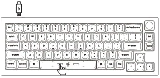
- Try factory reset by pressing fn1 +J +Z (for 4 seconds).
- Download the right firmware for your keyboard from our website.
Remove the power cable from the keyboard.
- Remove the space bar keycap to find the rest button on the PCB.
- Hold the reset key while plugging in the power cable and then release the reset key. The keyboard now will enter DFU mode.
- Flash the firmware with the QMK Toolbox.
- Factory reset the keyboard again by pressing fn1 + J + Z (for 4 seconds)
*Step by step guide can be found on our website
Q2 CUSTOMIZABLE KEYBOARD SPECIFICATIONS
| Specifications | | --- | | Layout | 65% | | Switch type | Mechanical | | Width | 121 mm | | Length | 327.5 mm | | Front height | 20 mm (without keycaps) | | Back height | 33.8 mm (without keycaps) | | Front height | 33.6 mm (with OEM keycaps installed) | | Back height | 45.6 mm (with OEM keycaps installed) | | Keyboard feet height | 2.4 mm | | Angle | 6.5 degree |
Q2 MECHANICAL KEYBOARD OVERVIEW
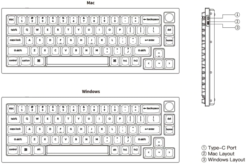
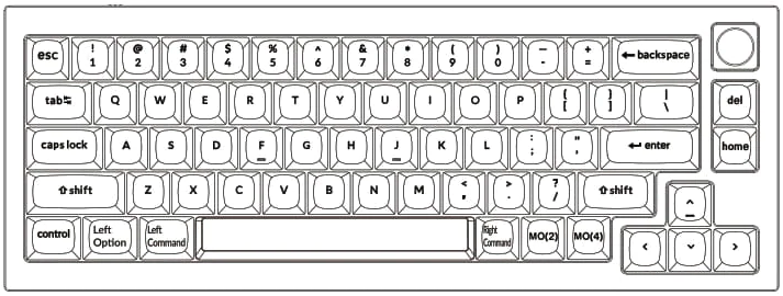
DEFAULT KEY LAYOUT:
LAYER 0: This layer will be activated when your keyboard's system toggle is switched to Mac.
LAYER 1: This layer will be activated when your keyboard's system toggle is switched to Windows.
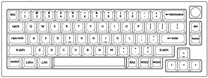
LAIt = Left Alt LWin = Left Windows RAlt = Right Alt
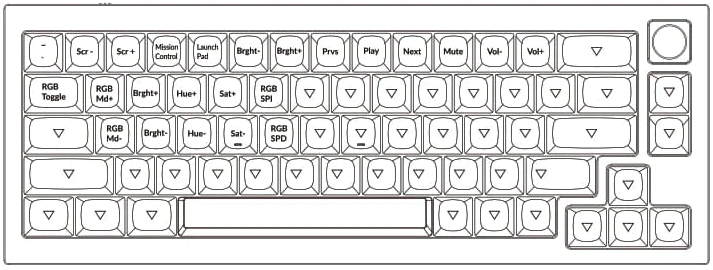
LAYER 2: This layer will be activated when your keyboard's system toggle is switched to Mac and press the fn1/MO(2) key.
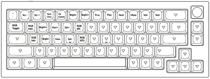
LAYER 3: This layer will be activated when your keyboard's system toggle is switched to Windows and press the fn1/MO(3) key.
LAYER 4: This layer will be activated when you press the fn2/MO(4) key.
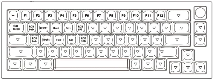
KEY DESCRIPTION
| Key Description | | --- | | Scr- | Screen Brightness Decrease | | Scr+ | Screen Brightness Increase | | Bright- | Backlight Decrease | | Bright+ | Backlight Increase | | Prvs | Previous | | Play | Play/Pause | | Next | Next | | Mute | Mute | | Vol- | Volume Decrease | | Vol+ | Volume Increase | | RGB Toggle | Turn Backlight on/off |
| RGBMd+ | RGB Mode Next | | --- | --- | | RGBMd- | RGB Mode Previous | | Hue+ | Hue Increase | | Hue- | Hue Decrease | | RGB SPI | GB Speed Increase | | RGB SPD | RGB Speed Decrease | | MO(1) | Layer 1 will be activatedwhen holding this key | | MO(2) | Layer 2 will be activated when holding this key | | MO(3) | Layer 3 will be activated when holding this key | | MO(4) | Layer 4 will be activated when holding this key |
Third-party input tools are not compatible with the keyboard.
Due to compatibility, versions, brands, and drivers of Windows/macOS, functionalities of third Party
input tools may be affected while using the keyboard. Please make sure your operating system and
drivers are up to date.
Certain fn keys or multimedia keys do not work under Windows/Android mode.
Functionalities of certain multimedia keys may be disabled due to compatibility, versions, brands
and drivers of Windows/Android OS.
Safety Precaution
Keep the product, accessories and packaging parts out of reach of children to prevent any accidents
and choking hazards.
Always keep the product dry to avoid corrosion.
Do not expose the product to extreme temperatures below -10°C (5°F) or above 50°C (131°F) to
preserve the lifespan of the keyboard.
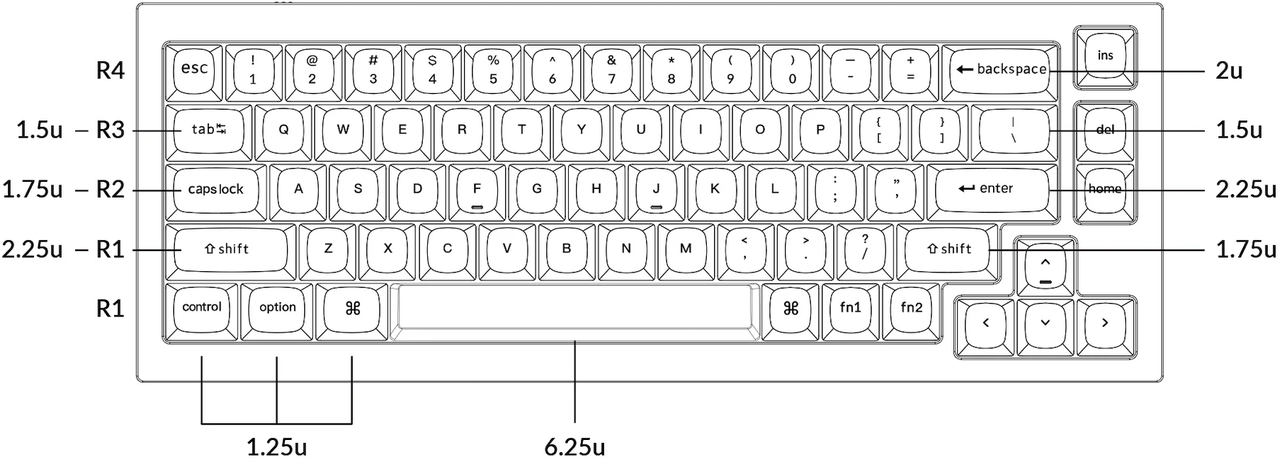
Keychron Q2 Keycap Size
Q2 Keyboard Plate File
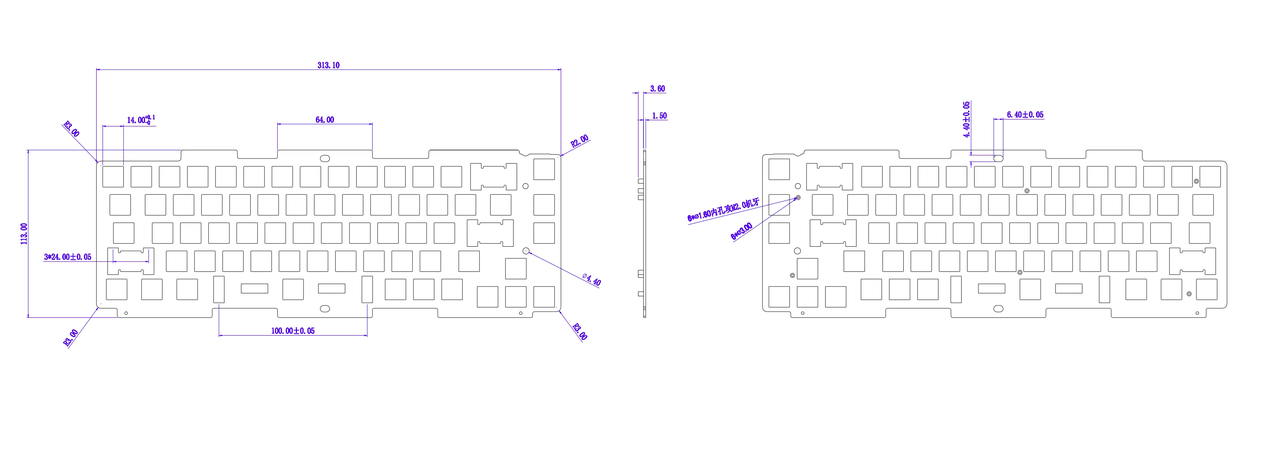
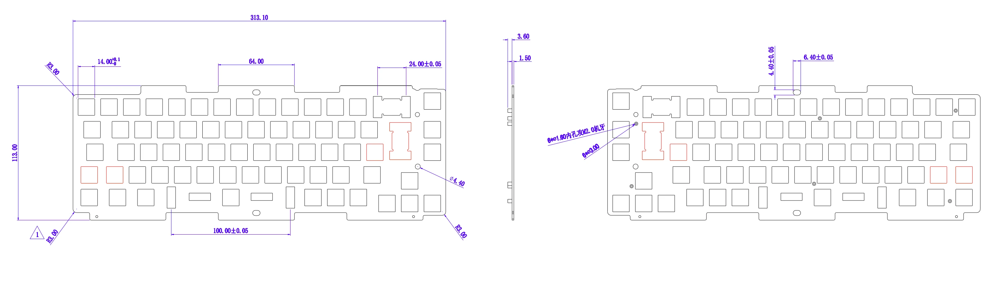
Q2 ANSI and ISO Layout Plate Download
Q2 ANSI Layout Plate dwg Format File Download
Q2 ISO Layout Plate dwg Format File Download
Q2 ANSI Layout Plate
Q2 ISO Layout Plate
Assembling guide
Step 1: Unscrew the screws on the bottom of the case by the hex key.
Step 2: Take the top and bottom of the case apart.
Step 3: Unscrew the screws on the daughter PCB.
Step 4: Take the main PCB and the top of the case apart.
Step 5: Remove the daughter-PCB from the main PCB.
Step 6: Unscrew the six golden screws on the PCB.
Step 7: Take the PCB, the foam, and the plate apart.
Please watch the video above to see how to disassemble a Q series keyboard.
You may contact support@keychron.com if a defect covered by the warranty arises in your product within the warranty period. Keychron will honor the warranty of our Q and V series keyboard (e.g.: Q1, Q2, V1, V2, etc.) by one of the following methods at our discretion:
- Defects of Q and V series keyboards have been caused by manufacturing: We will only replace the defective parts of the keyboard, not the whole keyboard, as its highly customizable and easy to be rebuilt.
- Defects of Q and V series keyboards have been caused by disassembling our product, improper installation, non-factory repairs/modifications, improper adjustment of the product, or neglect, including but not limited to “burn-in”, and similar wrongful use: We will NOT offer free service. We only offer paid service to replace the defective parts at your own cost (including the cost of parts, shipping fee and tax if applicable).
How to Replace the Plate on a Q Series Keyboard
Step 1: Unscrew the 6 golden screws on the back of the PCB.
Step 2: Take the PCB, foam, and plate apart.
Step 3: Prepare your new plate
Step 4: Install the nuts and metric threaded adapters onto the new plate.
Step 5: Assemble the new plate, foam, and PCB together.
Step 6: Screw the 6 golden screws back onto the plate.
Step 7: Install the gaskets onto the plate.
Please watch the video above to see how to replace the plate on a Q Series keyboard.
You may contact support@keychron.com if a defect covered by the warranty arises in your product within the warranty period. Keychron will honor the warranty of our Q and V series keyboard (e.g.: Q1, Q2, V1, V2, etc.) by one of the following methods at our discretion:
- Defects of Q and V series keyboards have been caused by manufacturing: We will only replace the defective parts of the keyboard, not the whole keyboard, as its highly customizable and easy to be rebuilt.
- Defects of Q and V series keyboards have been caused by disassembling our product, improper installation, non-factory repairs/modifications, improper adjustment of the product, or neglect, including but not limited to “burn-in”, and similar wrongful use: We will NOT offer free service. We only offer paid service to replace the defective parts at your own cost (including the cost of parts, shipping fee, and tax if applicable).
How to Install the Badge for a Q Series Keyboard
Step 1: Unscrew the screws on the back of the case.
Step 2: Unscrew the screws on the daughter PCB.
Step 3: Take the PCB and the top case apart.
Step 4: Assemble the badge onto the top case.
Step 5: Screw the badge into the top case.
Step 6: Take out the upright keycap and switch.
Step 7: Assemble the PCB and the top case back together.
Step 8: Screw in the daughter-PCB.
Step 9: Screw in the bottom case.
You may contact support@keychron.com if a defect covered by the warranty arises in your product within the warranty period. Keychron will honor the warranty of our Q and V series keyboard (e.g.: Q1, Q2, V1, V2, etc.) by one of the following methods at our discretion:
- Defects of Q and V series keyboards have been caused by manufacturing: We will only replace the defective parts of the keyboard, not the whole keyboard, as it's highly customizable and easy to be rebuilt.
- Defects of Q and V series keyboards have been caused by disassembling our product, improper installation, non-factory repairs/modifications, improper adjustment of the product, or neglect, including but not limited to “burn-in”, and similar wrongful use: We will NOT offer free service. We only offer paid service to replace the defective parts at your own cost (including the cost of parts, shipping fee, and tax if applicable).
Was this article helpful?
0 people found this helpful